Hydro Boost Install Diagram

Hydro-boost brake boosters use the pressure of the power steering pump to. Always refer to the vehicle service manual for specific installation and testing.
Proper diagnosis of hydro-boost related problems requires an understanding of how the system works. A typical hydro-boost is shown in Figure 1. The hydro-boost is plumbed in line with the steering gear. The power steering pump supplies pressurized fluid for both the power steering gear and hydro-boost. Spool Valve Fluid flow in and out of the hydro-boost is controlled by what is known as a spool valve.
Spool valves are used in a variety of hydraulic components, such as the valve body of an automatic transmission. A spool valve is basically a hollow cylinder with a number of rings machined into it (see Figure 2).
The surface of the spool valve is highly polished to form a sealing surface. The raised portions of the cylinder are called lands while the indentations are called annular grooves. Figure 3 shows a simplified spool valve positioned in a bore with three ports. The path of the pressurized fluid from port 1 is determined by the position of the spool valve. Software pencari crack dan keygen generator.
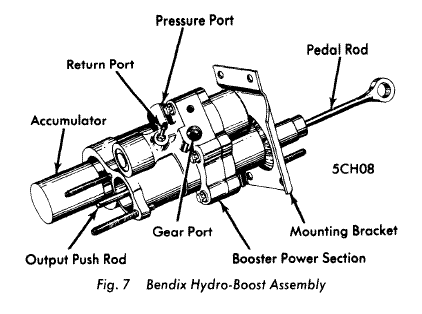
The spool valve is positioned in figure 4 to allow fluid flow from port 1 to port 2 while port 3 is blocked by land #1. Figure 4 shows the spool valve moved to the left which changes the fluid flow. The fluid flow is now from port 1 to port 3 with port 2 being blocked by land #2. The spool valve in a hydro-boost works in a similar fashion. Hydro-boost Construction Figure 5 shows a cutaway of a hydro-boost with all the major components labeled. These include the housing, power chamber, input rod assembly, a lever assembly, a power piston, spool valve assembly and an output rod. The housing is fitted with three ports as identified in Figure 6.
The spool valve fits into a precisely machined bore that is part of the hydro-boost housing as shown in Figure 7. The fit between the spool valve and the bore is such that it creates a seal while at the same time allowing enough fluid between the lands and bore to provide lubrication. The spool valve’s position is determined by the lever assembly which is connected to the input rod. Pedal Unapplied When the brakes are unapplied the spool valve is positioned as shown in Figure 8. In this position the pressurized fluid from the power steering pump is allowed to flow to the steering gear, but not into the power chamber. The spool valve vents the power chamber to the return line of the power steering pump reservoir. Pedal Applied Once the brake is applied, the input rod moves forward (left) to the power piston assembly.
The piston return spring is preventing the power piston and pin “A” from moving forward. This lack of movement causes the input rod to force the travel limiter valve assembly into the power piston which results in pin “B” moving forward. The lack of movement at pin “A” and forward movement of pin “B” causes the lever to pivot at pin “A”. The top of the lever moves forward (left) which results in moving the spool valve (See Figure 9). The forward movement of the spool valve closes the reservoir port which seals off the power chamber. Continued movement of the spool valve opens the pressure port from the power steering pump allowing pressurized fluid into the power chamber while at the same time maintaining the fluid flow to the steering gear. The pressure in the power chamber causes the power piston to move forward (left) which applies the brakes through the output rod (See Figure 10).
Pedal Released Once the brakes are released, the spool valve return spring pushes the spool valve back to its rest position. This vents the pressure in the power chamber to the power steering pump reservoir through the return line. The power piston and lever assembly are returned to their rest position by return springs which in turn brings the brake pedal back to an unapplied position. Back-Up Similar to the vacuum booster, the hydro-boost is equipped with a backup or reserve in case the source of pressurized fluid is lost. A failure in the power steering system, such as a broken hose, broken power steering pump drive belt, or failed pump, would result in a loss of pressure to both the hydro-boost and steering gear. The hydro-boost uses a high-pressure accumulator to store power steering fluid under pressure in the event of a failure. There are two types of accumulators used, some hydro-boost units use an external accumulator, while others incorporate the accumulator in the power piston.
The accumulator could be either of the spring-loaded variety or nitrogen-gas type. In the event of a loss of pressurized fluid, the accumulator will provide two to three power assisted stops.
Upon the first application of the brakes after an engine stall or loss of power steering, you would find approximately 60 to 75% of the normal assist available. If you were to release and apply the brakes again, you would find approximately 30% to 40% assist, then again approximately 10% to 20%, until you have depleted all stored reserve assist. Once you have depleted all of the stored pressure, the brakes will no longer have power assist and will be manual in their operations. During normal operation, the accumulator is charged by pump pressure though a check valve assembly (See Figure 11). The check valve allows fluid into the accumulator, but prevents it from escaping. When the pressure in the power chamber is lost due to a failure, the input rod linkage will override the power piston linkage and cause the check valve to be opened. The open check valve will release the stored fluid in the accumulator into the power chamber which will provide the power assist.